The network of runoff axes extracted from a DTM does not always reflect the true runoff pathways, as observed on the field. Ditches, roads and paths modify the direction of runoff, and their impact is not always captured by the DTM due to resolution issue. A SAGA tool has been developed to force the runoff direction.
The Fill DEM tool can be accessed from the Download tab and is contained in the WaterSed.zip zip file. If you follow the order of the tutorials correctly, you’ll find it in TUTORIAL/MODELE. It is called WS_Fill_DEM_v1.6.xml. Install the tool by dragging and dropping the .xml file into the SAGA GIS Tools window. To access the :
Tools tab <> Tool Chains <> WaterSed <> Fill DEM
To illustrate how it works, we’re going to force flow along a fictitious runoff axis.
Step 1. Vectorization of a runoff axis network
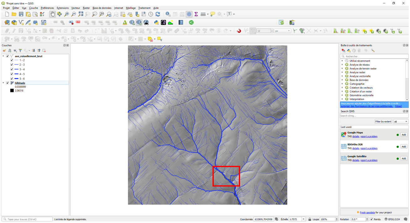
In Qgis or Arcgis, import hillshade.sgrd and axe_ruissellement_brut.shp. Zoom in to downstream basin (red square).
The runoff axis network shows that runoff from the farm road at (1) leaves the road at (2) to join the talweg. In addition, runoff from northern plot crosses the road at (3) and (4).

Field observations show that runoff collected by the farm track joins the talweg at (5).
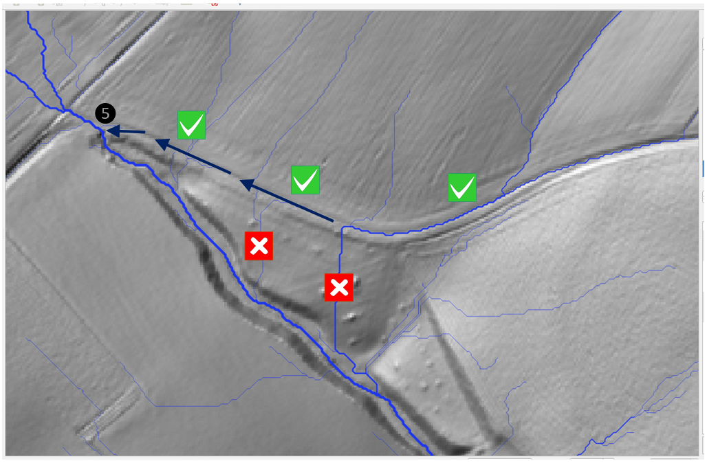
The aim is therefore to modify the DTM so that runoff flows along the axis described in the field. In this exercise, the agricultural road is the only modification made to the runoff axis network.
Create a new shapefile line layer with the name axe_ruissellement_modif.shp (Lambert 93 projection system).
/TUTORIEL/PREPROCESSING/TOPOGRAPHIE/axe_ruissellement_modif.shpCreate a first section representing the farm road, starting where the runoff axis leaves the road and running to (5).
Add the section representing the talweg from (5) to the watershed outlet (either by copying and pasting from axe_ruissellement_brut to axe_ruissellement_modif, or by digitizing using QGIS’s « Snapping » and « Activate trace » options).
It is imperative that each new section is connected to the watershed outlet. No section should be isolated!
It is not necessary to add the other runoff axes, as they will be recalculated after the DTM has been corrected. All you need to do is add the axis sections that will link the new axes to the basin outlet!
The axe_ruissellement_modif and axe_ruissellement_brut shapefiles are shown below.

Zoom in on the outlet (end of the talweg section). Check that the end of the section coincides with the DTM boundary mesh.

Step 2. Runoff axis network properties
In the WaterSed model, velocities are calculated differently on slopes and in networks of runoff axes that channel runoff (watercourse, ditch, sunken road, etc.). Flow is « diffuse » on slopes, while it is « concentrated » on roads.
In order to calculate the flow velocities, it is necessary to indicate the full width of each network section. This step details the method used to construct the runoff axis network width grid.
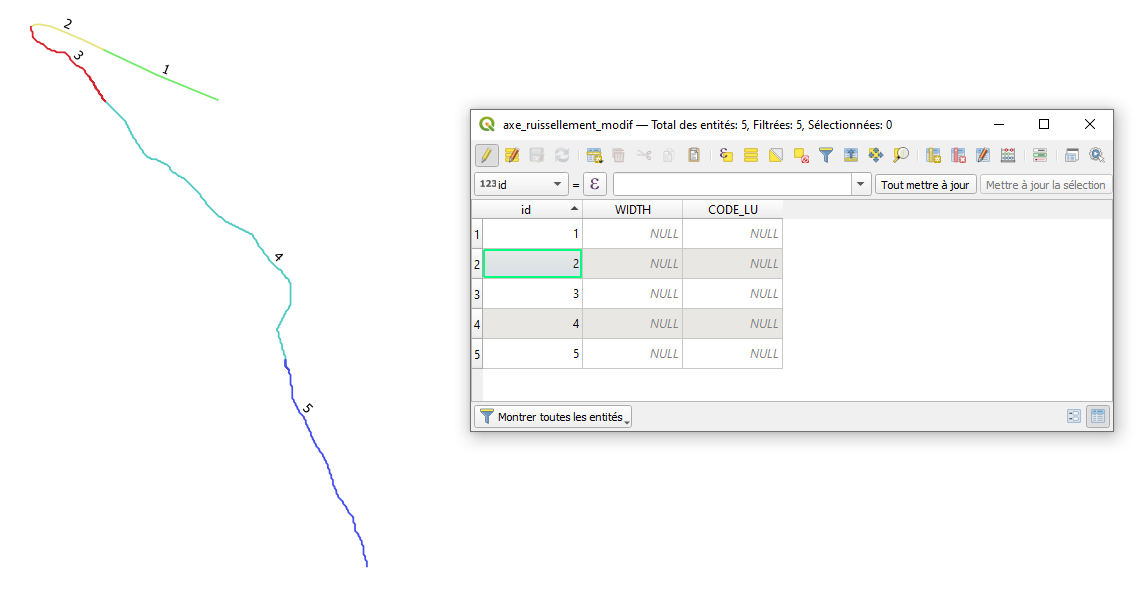
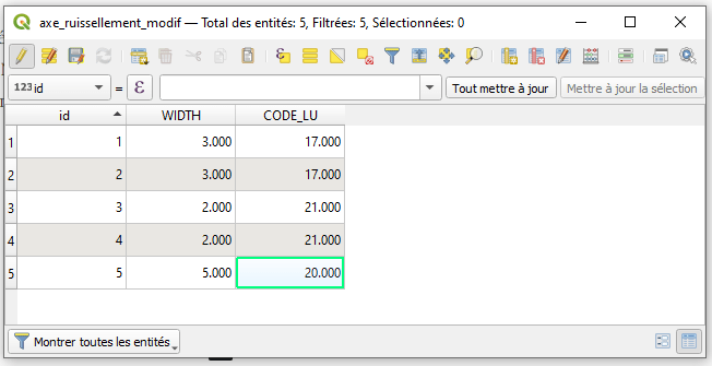
Switch to edit mode on the axe_ruissellement_modif shapefile. Open the attribute table and create two float (or decimal) fields. The first field is called WIDTH (width in meters) and the second field is called CODE_LU (unique code per runoff axis type; used in the soil and land use tutorial).
The shapefile axe_ruissellement_modif consists of 5 sections. Assign a unique identifier from 1 to 5 in the id field (create id field if necessary). The identifier for each section is shown below. Check that the sections and identifiers correspond to the following map.
In this example, the flow widths of the various sections are as follows:
- A 3m-wide path on sections 1 and 2
- A 2m-wide trench on sections 3 and 4
- A 5m-wide watercourse on section 5
In the case of slope flows (where flows are « diffuse » and not concentrated), the flow width corresponds to the DTM resolution. In our case, the DTM resolution is 1 m. In addition, it is necessary to assign a CODE_LU to each type of runoff axis. In this example :
- Path : 17
- Trench : 21
- Watercourse : 20
Edit axe_ruissellement_modif attribute table. Save changes and exit edit mode.
Step 3. DTM hydrological correction along predefined runoff axes
Return to SAGA GIS and import mnt_brut.sgrd et axe_ruissellement_modif.shp.
Launch Fill DEM.
Tools tab <> Tool Chains <> WaterSed <> Fill DEM
The Fill DEM tool has two functions:
- Hydrological correction of a DTM along predefined runoff axes
- Generate the runoff axis width grid required for the WaterSed model
The Fill DEM tool can be used in two ways:
In Case 1, this is a configuration where there is no runoff axis that concentrates runoff and/or modifies the direction of runoff (this is the case, for example, if the study area is limited to an agricultural plot). In this case, the tool performs a simple hydrological correction using the Fill Sinks XXL tool (Wang & Liu), with a minimum slope value (°). The tool requires a DTM Digital Elevation Model (m) as input and generates a corrected DTM Filled Digital Elevation Model (m) as output.
In the absence of a Runoff network shapefile, the tool creates a Network Width (m) runoff axis width grid with values of 0 over the entire study area.
In Case 2, this is a hydrological correction of the DTM with predefined runoff axes. The tool requires a DTM Digital Elevation Model (m) and a Runoff Network in shapefile format with a WIDTH field in the attribute table.
The tool also offers the option of incising a mound (embankment in the bottom of a talweg, bridge in a watercourse, etc.) according to a Breach shapefile section. Unlike Runoff Network, Breach does not require a specific attribute in the attribute table. Breach sections can be isolated and not attached to the basin outlet. If Breach is defined, Runoff Network must also be defined.
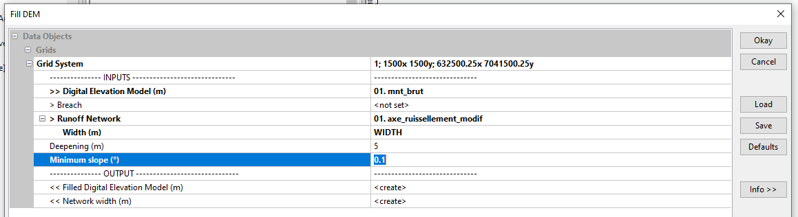
To force flows along predefined runoff axes, the tool will « deepen » the DTM at the locations of these axes. The Deepening option (m) is used to set the depth of overcutting. Minimum Slope (°) defines the minimum slope between meshes (identical to the Fill Sinks XXL tool).
The output of the tool is a hydrologically corrected DTM based on the predefined Filled Digital Elevation Model runoff axes (m) and a Network Width grid (m) (value 0 outside the network).
Load mnt_brut from Grid System. Load mnt_brut in the Digital Elevation Model line (m). Load axe_ruissellement_modif in the Runoff Network line and specify the Width field in the Width line (m). In this example, the overcut value used is 5m and the minimum slope is 0.1°.
The Filled Digital Elevation Model (m) grid appears in the Data tab. Overwrite the old mnt_fill and save the new DTM as mnt_fill.sgrd. Also save the Network Width grid (m) as network_width.sgrd.
/TUTORIEL/PREPROCESSING/TOPOGRAPHIE/mnt_fill.sgrd
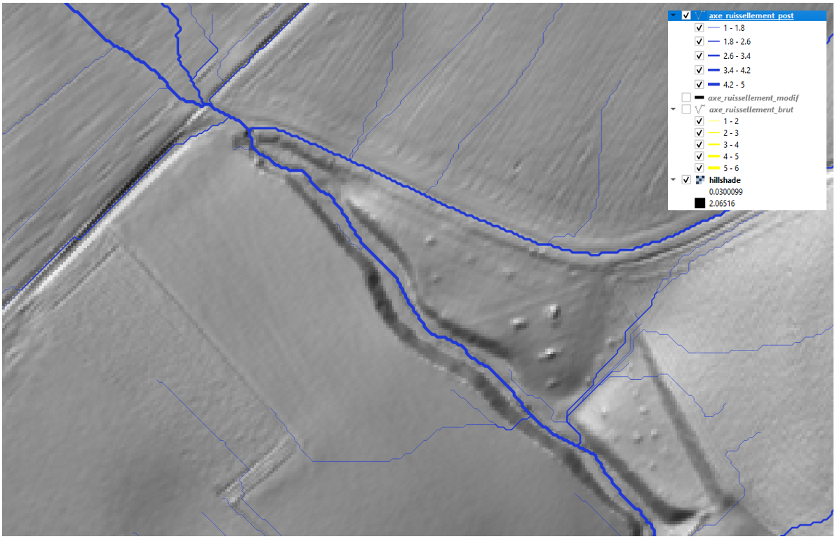
/TUTORIEL/PREPROCESSING/TOPOGRAPHIE/network_width.sgrdRestart the runoff axis mapping step using Channel Network and Drainage Basins (still with a threshold of 5). Save the Channels shapefile as axe_ruissellement_post.
/TUTORIEL/PREPROCESSING/TOPOGRAPHIE/axe_ruissellement_post.shpImport this new layer into QGIS or ArcGis. The new network of runoff axes reproduces the impact of the farm road!